2.1 GPIO - LED Blink
This tutorial instructs you how to use ESP32 to blink an LED. This is one of the first tutorials that beginers learn.
Introduction
LED
A light-emitting diode (LED) is a semiconductor device that emits light when an electric current flows through it. It has unidirectional conductivity and can emit light with a current of about 5mA. The greater the current, the brighter the brightness.
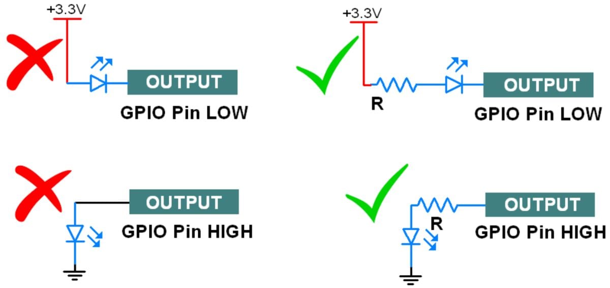
However, if the current is too large, the diode will be burned. Generally, we control it between 3mA-20mA. So we will connect a current-limiting resistor in series with the LED pin to limit the current.


GPIO
General-Purpose Input Output (GPIO) is a digital pin of a controller or module. It can be used as input or output for various practical applications.
If we want to read the switch’s state, sensor data, etc then we need to configure it as input. And if we want to control the LED brightness, motor rotation, show text on display, etc then we need to configure it as output. ESP32 board has various digital IO pins which can be used for input/output devices.
Hardware Circuit
1. Parts Required
Here’s a list of the parts to you need to build the circuit:
ESP32-S3-N16R8 x 1
5 mm LED x 1
330 - 1000 Ohm resistor x 1
Breadboard
Jumper wires
2. Wiring
Before proceeding, you need to assemble a circuit with an LED. We’ll connect the LED to GPIO 5 and the pushbutton to GPIO 4.

Be sure to connect a resistor, otherwise the LED will burn out due to excessive current.
Coding and Testing
Make sure you have it installed PlatformIO extension in VScode. (Ref: Install PlatformIO procedure)
Create a new project in PlatformIO IDE and choose ESP32-S3-DevkitC as the Board.

1. Code for LED blink
Copy the following code to your PlatformIO IDE.
2. Uploading the Code
Note that here we use the ESP32-S3-N16R8 board, and choose the ESP32-S3-DevkitC when create the project. Please config the platformio.ini file before upload the code.
Go to Devices > Serial to check the COM port that the ESP32 is connected to. Then, press the upload button and wait for the “Done uploading” message.
If you see a lot of dots (…__…__) on the debugging window and the “Failed to connect to ESP32: Timed out waiting for packet header” message, that means you need to press the ESP32 on-board BOOT button after the dots start appearing.
Summary
With this getting started guide, you’ve learned how to read digital inputs and control digital outputs with the ESP32 using Arduino IDE.
Also, we connect the ESP32-S3-WROOM-1-N16R8 and use PlatformIO to program it.
Appendix - GPIO Cautions:
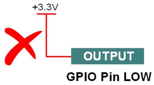
If the GPIO pin defines as an OUTPUT LOW then don’t connect this pin to VCC, it will get short circuit and large current flow will damage your controller or GPIO pin.

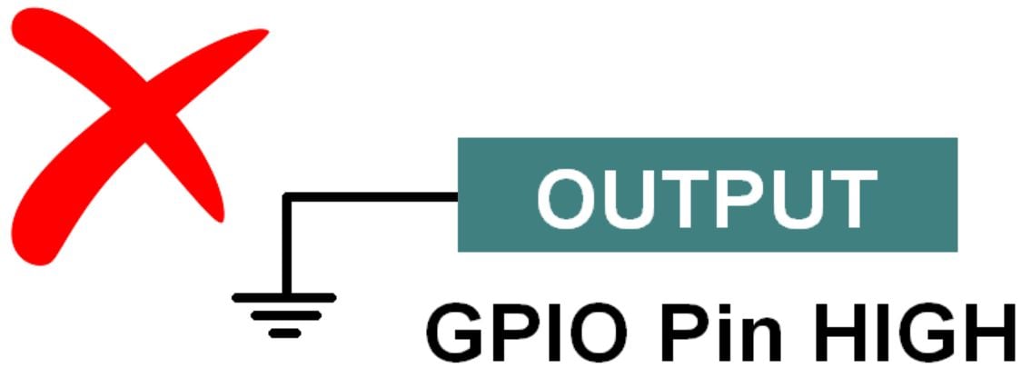
If the GPIO Pin defines as an OUTPUT HIGH then don’t connect this pin to Ground, it will draw large current which will damage your controller or GPIO pin.

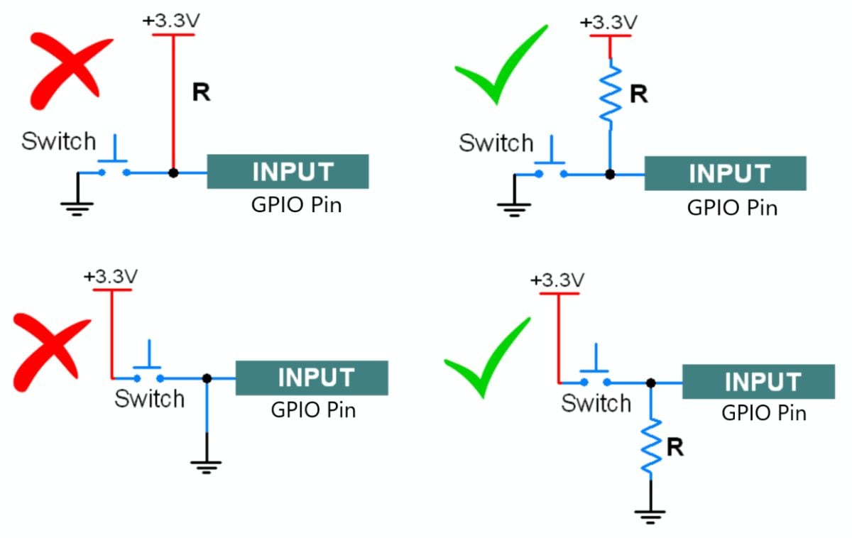
For switch connection always use a pull-up or pull-down (based on your coding logic). Always use pull UP/pull down resistor inside the microcontroller or connect an external resistor.
Don’t connect the direct VCC pin to the GPIO pins, otherwise it will short the power supply when you press the switch.
Kindly check following scenarios:

While interfacing the led always connect a series resistor to limit the current, otherwise LED will burn.

Last updated